
Are Ferrite Beads Needed in Today's Electronics?
By ZM Peterson • Jun 27, 2021I’ve seen some odd guidelines on the use of ferrite beads in PCB design, including some guidelines that are likely to create major EMI problems. Ferrite components are very useful when used correctly, but they are not a solution to every EMI problem. Their principle use is as an EMI filter on power inputs, often on the input to a common-mode EMI filter circuit.
Outside of filtering noise on power line inputs, ferrites are sometimes used in odd ways in an effort to filter EMI or suppress reception of EMI. If not used properly, a ferrite can create new signal integrity, power integrity, or EMI problems. What’s worse, many application notes give bad guidelines on the use of ferrite beads in a new design, again creating EMI problems through several possible mechanisms. If you’ve selected some components for use in your board and you’re under the impression that you need a ferrite bead, read these guidelines first to see whether use of ferrites is necessary.
How Ferrite Beads Work
First, when we use the term "ferrite bead," we have to be very specific because we could be referring to two possible devices:
- Ferrite cores, which wrap around a power cord to provide common-mode noise filtering through inductive coupling
- Chip ferrite beads, which come in an SMD package and mount directly to a board to provide differential-mode filtering, although some versions can provide common-mode filtering
There are other types of ferrites, but they all operate on similar principles. All SMD ferrite beads and ferrite cores operate like inductors and provide inductive impedance up to high frequencies, with an impedance peak located from ~100 MHz to GHz frequencies, depending on the physical size and materials used to make the component. Ferrite beads are not bead-shaped at all; they are toroids or hollow cylinders wrapped with wires, just like a typical inductor. At frequencies of the impedance peak, ferrites exhibit capacitive impedance, so the overall impedance curve exhibits bandstop behavior over a broad bandwidth. The example below shows the impedance curve for HF50ACB321611-T from TDK, an SMD ferrite bead that is designed for DC signal lines.

Example impedance curve for an SMD ferrite bead from TDK. The right image shows an equivalent circuit for a ferrite. [Source: HF50ACB321611-T datasheet]
Typical Use of Ferrite Cores
Ferrite cores are typically used on a DC power cord to provide common-mode noise filtering. Due to the material properties and behavior of ferrites, they exhibit magnetic saturation and hysteresis, so physically larger ferrites are needed to accommodate larger powers and more intense noise filtering, particularly harmonic filtering in high power systems. More elaborate methods are used to ensure greater noise rejection than using a ferrite on its own, namely common-mode and differential-mode filter circuits on the board and PFC circuits.
Where Not to Use SMD Ferrite Beads
Other typical places you’ll see ferrite beads are as all-purpose filter components, something which I do not recommend. Whenever we get a request to rework a board for EMI failure, improper use of ferrites are sometimes found to be part of the problem. There are two very common situations where I would say ferrite beads should not be used.
As a series element on a DC power bus. When you understand what contributes to PDN impedance, you’ll understand that inductance is exactly what you don’t want on a power bus. Placing a ferrite bead on a power bus (such as the output from a switching regulator), was probably fine in the 1980s, but it should not be done in today’s modern devices. Even relatively low-speed components will still experience the same types of power integrity problems formerly reserved for high speed PCBs like motherboards and fast add-in cards if PDN impedance is too high.
In this instance, the ferrite bead is intended to produce low-pass filtering behavior, allowing only DC power to reach the load. The problem is that ferrite beads are not low pass filters, they are band stop filters. Because the transient current pulse drawn into a PDN has infinite bandwidth, the current draw excites a transient oscillation on the power bus that leads to high-frequency voltage ripple. This problem would have happened without the ferrite bead, and adding the ferrite actually makes this problem worse.
Tieing split ground planes together. First, of all, you should never carve up ground planes unless you need galvanic isolation in a power system. In every other instance I’ve seen, you create a new EMI problem by trying to provide isolation, normally in mixed-signal systems that didn’t need any additional isolation to begin with. When this is done, the designer will then bridge the two ground regions with a ferrite bead under the idea that only DC power will be bridged across the gap. The problem is that any signal routed over the gap will still see a very high impedance return path due to the ferrite’s bandstop behavior (see the example curve above). This then causes strong radiated emission from the region where the signal propagates.
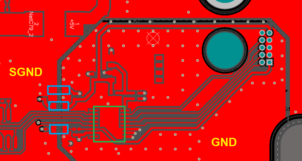
Example of bad grounding from a recent project. In this example, ferrites were used to bridge the gap between these two ground nets and provide a return path with low impedance. However, the return path had high impedance and contributed to broadband EMI.
In these situations, the ferrite bead is usually added to solve an EMI problem that was created through bad layout practices. Some of these layout practices, like routing over uniform ground planes or designing with a low-impedance PDN, are now standard in almost every digital design. Although ferrites are sometimes misused in high speed/high frequency PCBs, there are some instances where the use of a ferrite bead or other ferrite materials are appropriate, particularly for providing EMI shielding.
Alternative Ferrites for EMI Reduction
One thing I’ve noticed is that many designers are unaware of the value of ferrites in various applications, especially in EMI shielding. There are other ferrites and shielding materials that can be used for shielding or filtering aside from ferrite beads, and these components can be valuable if used properly. These include:
- Ferrite plates: These are plates or disks of ferrimagnetic material that can be mounted on or near specific components on the board. These materials will counteract EMI from fast switching via inductive coupling.
- Chokes: These come in the common-mode or differential-mode variety, depending on the winding direction around a ferrite core, and they can be mounted directly on a PCB with 2-wire connections. This should be contrasted with a ferrite core on a power cord, which has no windings and suppresses both types of noise simultaneously.
- Shielding cans: These mount directly to the board and can be grounded to the enclosure or an internal GND net. Some companies can produce custom shielding cans that mount directly to the board surface and provide a complete enclosure around components.
- Elastomers and tapes: These should be used as a last resort after adding EMI filter circuits and ensuring you’ve implemented the best layout practices to ensure low EMI. These materials can target mating surfaces and the board edge, as well as any small gaps in an enclosure where needed.
Although there is a range of EMI shielding solutions on the market, the board layout should always be constructed with EMI in mind. From a CSWaP perspective, you should aim to forego these additional shielding materials as they will increase costs and weight in the system. An experienced design firm can help you weigh the different options and find the best solution to ensure EMC compliance.
Don’t take chances with ferrite bead usage in your next PCB. Instead, work with an experienced design firm that understands how to design and build modern electronics while staying compliant with industry standards. If your company is pushing the limits of telecom, data center, aerospace systems, and low power embedded systems, it pays to work with an experienced electronics design firm. NWES helps private companies, aerospace OEMs, and defense primes design modern PCBs and create cutting-edge embedded technology. We've also partnered directly with EDA companies and advanced ITAR-compliant PCB manufacturers, and we'll make sure your next high speed digital system is fully manufacturable at scale. Contact NWES for a consultation.
Ready to start your next design project?
Our Clients and Partners


