
EMI Filter Circuit Design for Your Next PCB
By ZM Peterson • Jan 29, 2020EMI has been the bane of many designs and will affect your product’s ability to pass EMC certification tests. Your design needs to have some resistance to noise, as well as emit low noise to be compatible with FCC and EU requirements. Suppressing EMI radiated to external devices can be a difficult task, while suppressing received EMI requires an EMI filter circuit design on some critical components.
The two principle types of time-invariant linear filter circuits are passive and active EMI filter circuits. These circuits can be placed on a PCB as discrete components, or they can be lumped into an integrated circuit. Some SoCs or specialty ICs will include an integrated EMI filter circuit design that is specifically designed for a particular application. In addition, filter circuits will target specific types of noise, either common-mode or differential-mode. When you think about it, all currents in a typical circuit diagram (e.g., a single-ended interconnect) are differential-mode, but the complex structure of a PCB can allow common-mode currents to flow through a PCB. Let’s look at how these different types of filters work and how they provide resistance to EMI.
Common-Mode and Differential-Mode EMI Filter Circuits
Before showing some effective types of EMI filter circuits, we should consider how filter circuits target different types of noise. I've never seen anyone state this explicitly, but it deserves to be stated: the typical filter circuit diagrams you see involving RLC elements are all differential-mode filters. This is the case simply because circuit diagrams don't consider the physical layout of circuits, or presence of other elements in a system, such as a nearby floating conductor or ground reference that is not part of a circuit. That being said, you can still use circuit diagrams to show how EMI filter circuits are constructed to address common-mode noise that might be present on the input or output of a system. In general, you'll need to consider both types of noise in your system when you're aiming to pass EMC compliance testing. Also, EMI filter circuits or components should be the first place to start removing noise. Once EMI filter circuits fail and changes to the board layout fail, you can look at more heavy-duty measures like on-board shielding or enclosure shielding materials.
Passive Filters for Differential-Mode Noise
As the name suggests, passive filters make use of passive circuit elements to provide filtration over broad or narrow frequency bands. It should be noted that most filters are primarily passive circuits, althought the filters shown below can be combined with an active filter circuit (an example is shown later). These filters are easy to construct as higher-order filters without requiring active devices. This keeps power consumption low and component costs low. These filters can also be cascaded to provide multi-band filtration (i.e., for a wideband antenna). As long as you are operating below the self-resonance frequencies for the discrete components in your EMI filter circuit design, your filter’s behavior can be reliably predicted using the basic series and parallel impedance equations.
The simplest way to place this type of EMI filter circuit in your board is with capacitors and inductors. These components will provide reactive impedance to your system and can be tuned to desired frequency ranges simply by adjusting the component values. These circuits are quite useful for removing EMI from specific frequency ranges. Some common applications include removing radiated EMI from a noisy clock or from another analog component that emits strongly at specific frequencies. The table below shows some common configurations. Any of these circuits can be easily analyzed with SPICE simulators.

Wideband EMI filter circuit design with inductors and capacitors
One important point to note when these cirucits are cascaded is the interaction between them, particularly when the filters and their traces are electrically long. This means a signal in one portion of the cirucit will interact with the signal in a different portion of the circuit, and this produces the complex higher-order behavior you would see in a SPICE simulation; this is shown in the below simulation results, where a complex resonance structure can be seen in a transfer function. If you're considering propagation in these circuits, their electrical behavior is more complex and should be examined with a more specialized time-delayed SPICE simulation or a field solver.
Narrowband Differential-Mode EMI Filtering with Passives
Although arranging passive components in series/parallel configurations is quite easy from a design standpoint, the operation of these filters may not always be intuitive, especially when you are aiming for multiband filtration. Take a look at the image below for an example where mutual resonance between a multiband filter creates an additional resonance. In this filter design, there is a desired stopband that needs to be filtered, and there is a pass band. The filter is cascaded using linear elements. The problem with this type of filter is that the two sections of the filter can mutually resonate, which creates a second passband in the transfer function and the output voltage. This can be clearly seen in the output voltage (purple curve). The stopband can be seen in the cyan curve and is centered around ~1.4 MHz.

Example cascaded bandpass/bandstop EMI filter circuit design created in Altium Designer.
They type of filter shown above is still useful as an EMI filter circuit for removing noise between 1 and 2 MHz. In particular, if you know there is a noise source near ~1.4 MHz, that noise will experience ~100 dB attenuation in the desired stop band. You can then use one of the two passbands to pass your desired signal and even apply gain. This is one way to provide some filtration and gain on the output a transceiver, mixer, antenna, or other RF component using only passive linear elements (note: be careful with impedance matching!).
Passives for Common-Mode Noise
So far, we've looked at differential-mode filters, but common- mode noise is arguably more important. This is because radiated EMI produced from circulating common-mode currents can be something like ~100x as intense as radiated EMI produced from differential-mode noise currents. This is compounded by superposition of radiated electromagnetic energy when common-mode currents circulate along multiple conductive paths in the same plane. This is one reason so many guides on EMI filtering and suppression focus on common-mode noise rather than differential-mode noise. However, just like an errant ground plane near your circuitry can couple noise around your board, it can also be use to remove common-mode noise with some passive circuit elements.
In general, there are three possible ways to eliminate common-mode noise in a circulating loop or on a pair of coupled lines:
- Shunt the noise to the nearest ground via a low-impedance path. This is one reason we ground a chassis to earth; any noise coupled into the chassis from high dV/dt signals will have a low impedance connection back to earth.
- Use a high impedance element in series with the noise to dissipate all of its power across that element rather than across some sensitive circuit. This only works when the load impedance is much lower than that of the series element at frequencies above DC. This is how a common-mode choke works: you drop all the energy as reactive power in coupled inductors so that none of the energy is dropped across the downstream load.
- Change the topology of the circuit so that any noise that is coupled to the circuit does not appear as common-mode. Changing your grounding strategy so that common-mode noise is lost to earth or some other reference qualifies as changing the circuit topology.
The example below shows a typical common-mode + differential-mode filtering stage on the input of an AC mains line. The pair of capacitors satisfies a low impedance shunt path back to the chassis, and the common-mode choke provides a series high impedance element that dissipates common-mode noise before it reaches the load. The other parallel capacitors function as standard differential-mode noise filters.

Example common-mode + differential-mode EMI filter circuit design created in Altium Designer.
Active Filters
More complex filter circuits can include op-amps to provide linear or non-linear broadband filtering. These types of circuits are not band-limited in the same ways as a passive EMI filter circuit design. Instead, the active components can be the limiting factor governing EMI suppression as they have some well-defined bandwidth. Active filters are constructed using op-amps, transitor circuits, or more complex circuitry, although op-amp circuits are most common. The great thing about these circuits is they can be easily configured as higher order filters for common-mode and/or differential-mode noise. This provides a simple way to filter out near-field EMI in the design using discrete components with small footprint. Note that the near-field distinction is critical here as EMI will be spread across the entire circuit in this regime.
The design below provides common-mode and differential-mode noise suppression over a broad bandwidth by simply using some capacitors and resistors along with an op-amp. The design shownn below is basically a form of differential receiver. All differential receivers are a form of common-mode filter, it's just that they are normally connected to some logic, so we don't call them EMI filter circuits. Differential input amplifier circuits, such as an op-amp, also take the difference between two inputs, so they can provide common-mode noise rejection as long as the noise phase difference between the two inputs is negligible over a broad bandwidth.
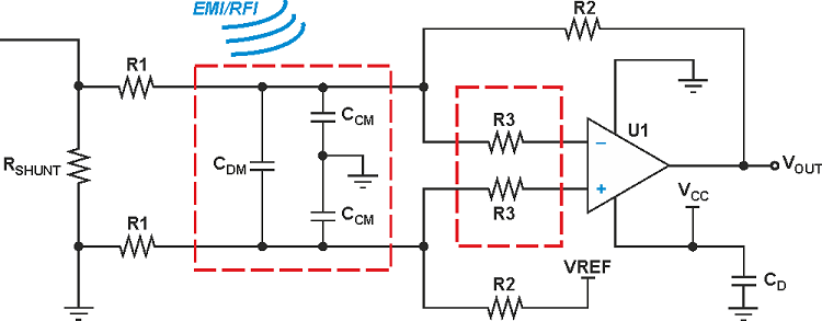
EMI filter circuit design with op-amp and RC elements. Image source.
Designs like this are easy to analyze; take a look at the reference link to see how to analyze the above EMI filter circuit design. At the ultra-high frequency level (i.e., microwave and mmWave frequencies), parasitics in your components and board start to become critical. Your passives will stop behaving as ideal components due to self-resonances; your capacitors will start exhibiting inductive impedance, and your inductors will start exhibiting capacitive impedance. Be sure to check the self-resonance frequencies of components when designing EMI filters to eliminate strong high frequency noise from specific sources.
If you need a PCB design firm that specializes in EMI filter circuit design, look no further than NWES. We have experience working with a variety of systems and designing for specialized applications. We’re also a digital marketing firm, and we can help you market your new product and reach your target audience. Contact NWES today for a consultation.
Ready to start your next design project?
Our Clients and Partners


