
SerDes Design: Physical Channels and Signaling
By ZM Peterson • Dec 1, 2019Data centers are responsible for today’s data-driven lifestyle. As the volume of data increases, and as more devices are connected to the Internet, there is a growing need to move data between servers and to end-users at a much faster rate. This has made SerDes design increasingly complicated and important.
Designers who create architecture for data center environments will soon be facing signal integrity problems that were formerly confined to mmWave devices. This is in addition to the typical signal integrity problems that are found in other digital systems. Here’s what designers need to understand about SerDes design, both at the physical channel level and in terms of signal integrity.
What is SerDes Design?
A serializer/deserializer (SerDes) is used to convert incoming parallel data into serial data. This data is sent over a physical channel (such as copper twisted pair, fiber, or a backplane), where it is received as serial data. The receiver then converts this data back to parallel data. This allows designers to speed up data transmission between two points in a system without increasing the number of pins on a component. The primary application for SerDes design is in data centers, where SerDes architecture is forced to handle higher data rates and more links.
The functional architecture and the signaling requirements at each end of a SerDes channel are shown below. In this image, I’ve only shown Tx and Rx ends of a channel as being unidirectional, however COTS transceivers at each end can make a single link bidirectional (full duplex).

SerDes channel architecture
Signaling in SerDes Design
With network switch speeds in data center environments doubling approximately every 24 months, we can expect to see 25.6 Tbps bandwidth on 256 full duplex 100 GbE links. This is all enabled by high speed SerDes design between Rx and Tx ASICs over a PCB and copper/fiber. With copper generally failing over any useful range beyond 25 Gbps, everything is moving to fiber to support greater data rates and higher bandwidth switches.
The move from 25 Gbps to 56 Gbps links was driven by a change from non-return to zero (NRZ) signaling to pulse amplitude modulation (PAM-4) signaling. This effectively doubled the data rate without requiring a doubling of clock speeds or a doubling of the number of links. This also forces designers to rethink the way signals are routed along a PCB through a channel, as PAM-4 uses a sinusoidal low frequency baseband signal to modulate the amplitude of a stream of pulses. The Tx and Rx ASICs used in SerDes need to output the modulating baseband signal as well as a stream of pulses, which turns a typical digital SerDes channel into a mixed-signal environment.
The use of multi-level signaling, whether on-board or over some other medium like fiber, creates greater need for pre-emphasis and equalization at the receiver side, as well as more complex transceiver construction for full-duplex communication. If you’re designing an equalization scheme, even a simplistic equalization scheme, accurate modeling of connectors and the substrate attenuation spectrum (i.e., substrate dispersion) are critical for ensuring signals can be properly decoded at the receiver.
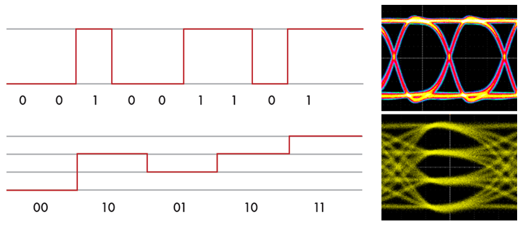
NRZ vs PAM-4 signaling
I’ll discuss the various equalization methods used for SerDes design in an upcoming article. For now, let’s take a look at some important signal integrity considerations in SerDes channels.
Signal Integrity in SerDes Channels
In terms of signal integrity and physical channel design, the baseband signal that is used for modulation is quite low compared to the knee frequency of the digital pulses transmitted in NRZ and PAM-4. If you properly design your system with signal integrity and power integrity in mind up to mmWave frequencies, you’ll be able to handle the lower frequency baseband signal without significant problems.
Your signal switching rates will be quite high with fast rise time compared to typical devices on other PCBs, which concentrates power in a higher range of frequencies. SerDes channels are generally routed as differential pairs, which eliminates radiated EMI. This leaves impedance control as an important design parameter when routing a SerDes design on your PCB. As long as your SerDes transmission line and stackup are designed properly, the remaining important aspect of impedance control in your board is the use of vias.
In general, you should minimize the use of vias on a high speed PCB. Systems operating at mmWave frequencies can exhibit insertion loss spikes at vias if layer transitions are not routed with an eye towards maintaining a continuous return path. Similarly, mis-sized vias will present a large impedance mismatch, which leads to signal reflections. Add to this the fact that the impedance of a via is not constant throughout the signal bandwidth, and you have the potential for serious signal degradation in a SerDes channel. Your impedance spectrum could appear as inductive (low pass) or capacitive (high pass), depending on the via size. This will also affect the choice of equalization used in the channel.
In addition to impedance control, you’ll need to consider attenuation in your board. The primary source of attenuation beyond insertion and return loss is dielectric losses due to the substrate. You should use a low-loss laminate (Isola or Rogers laminates are idea), i.e., the loss tangent should be as low as possible at the relevant signal bandwidth (spanning from the switch rate up to the signal’s knee frequency).
Finally, resonances in the substrate’s fiber weave can be excited by the oscillating signal in a SerDes channel. This creates a source of cavity emissions in your substrate, which become quite prominent when measured from the edge of the board. These substrate resonances have lower frequency when the fiber weave is loose, making them easier to excite by digital signals in a SerDes channel. A tight fiber weave will have a lowest order resonance in the 10’s of GHz range, which nicely eliminates any cavity emissions from your substrates. The fiber weave also presents a source of skew, which contributes to intersymbol interference seen at the receiver. This places greater pressure on properly designed equalization schemes at the receiver to recover transmitted signals.
There is so much to discuss around SerDes design that I can’t cover everything in a single blog post. In addition to equalization methods, I’ll also look at methods for modeling SerDes channels and discuss some important aspects of connector termination in some upcoming articles.
With the signal integrity and power integrity problems that can arise in SerDes design, you’ll want to work with an experienced design firm that offers cutting-edge PCB design services and technology research services for electronics companies. If you’re interested in seeing what we can do for you, contact NWES for a consultation.
Ready to start your next design project?
Our Clients and Partners


