
What is Input Impedance?
By ZM Peterson • Apr 30, 2020This is one of those basic questions that is often asked in the context of transmission lines and integrated circuits. From everything I have seen online, it’s also horribly explained. Textbooks do students a dis-service by not relating this important topic back to signal behavior in multiport networks, and most online explanations simply present the definition from a transmission line.
If you want to know what is input impedance, you need to think about circuits in terms of entry and exit of different signals. As signals move between different blocks of a circuit, they encounter some apparent impedance as they move into the network. The input impedance seen by a signal depends upon the totality of elements in the network, not just the circuit element seen at the input port. If you can determine the input impedance of an electrical network, you can successfully design high speed electronics and RF devices without signal degradation.
What is the Input Impedance of an Electrical Network?
When a propagating electrical signal enters an integrated circuit, waveguide, transmission line, or other electrical network, it "sees" a certain impedance that resists generation of current in the electrical network. Any circuit that receives a voltage signal will provide some resistance to the propagating signal (e.g., a digital signal, pulse, or sinusoid). This then determines how much power in the signal reflects from the circuit and how much is transmitted into the circuit.
For a general electrical network, there is no closed form solution for the input impedance. The various elements inside of a component on a PCB, a circuit block in an integrated circuit, or any other electrical network combine to determine the input impedance. For simple electrical networks of linear passive components (resistors, inductors, and capacitors), the input impedance is simply the equivalent impedance of the network determined using series and parallel rules. Note that not all circuits have a closed form solution for this equivalent impedance. For circuits with nonlinear elements (e.g., transistors and diodes), the input impedance will depend on the voltage level of the signal. Also, for a waveguide or transmission line, the input impedance depends on the geometry of the structure, which means impedance matching is not always a simple matter of placing a termination network.
To understand what is input impedance, take a look at the example diagram below. In this diagram, a source (Vs) outputs a digital signal. The source has some equivalent output impedance (Zout) and travels to the electrical network. When the signal reaches the input port of the network, the signal might reflect off of Z1. However, the behavior of the signal does not just depend on Z1. Instead, it depends on the value of Zin. The elements in the network (Z1-Z4) combine in some way to create the input impedance Zin. Note that Z1-Z4 could be transmission lines, passive elements, nonlinear components, or any other component with defined impedance.
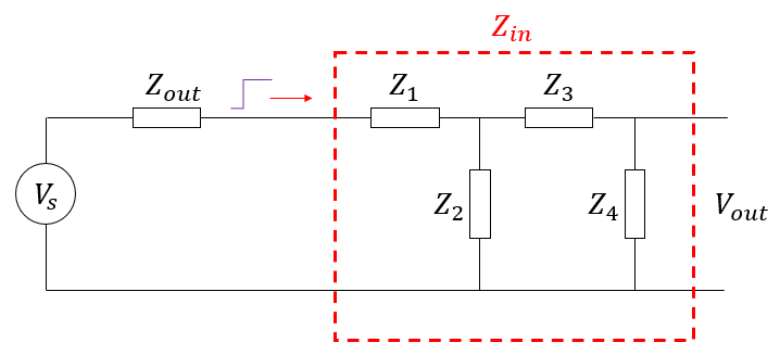
Example electrical network and its input impedance.
Signal reflection does not depend only on Z1 because the various components in the network couple together through the electromagnetic field. Components Z2-Z4 also provide some impedance contribution to Z1, and the four elements combine to produce an input impedance Zin. The goal in calculating the input impedance is to ensure impedance matching between the source and the receiver network. Maximum power transfer and zero reflection occur when the output impedance of the source is the complex conjugate of the network’s input impedance.
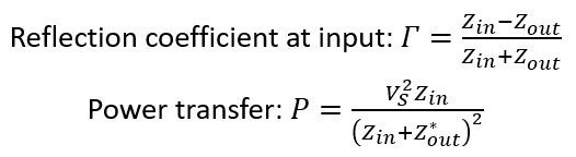
Conjugate matching to the input impedance sets the reflection coefficient to zero.
From here, your goal is to determine the input impedance of your network, which can be complicated analytically. Techniques like load-pull analysis are used with amplifier circuits to determine best impedance matching that tries to balance minimized reflection with maximized power transfer. Note that the voltage and current distribution throughout the interior of the circuit can be quite complex. Waves inside the circuit can still reflect between components, different components might be connected with transmission lines that have length-dependent impedance, and all this behavior can be a function for frequency (i.e., for reactive components).
Finally, the circuit will have defined output impedance that is not necessarily equal to its input impedance. The output impedance is equivalent to input impedance seen from the output side (i.e., looking into the circuit from the Z4 side of the network), which assumes reciprocity in the circuit.
Measuring Input Impedance
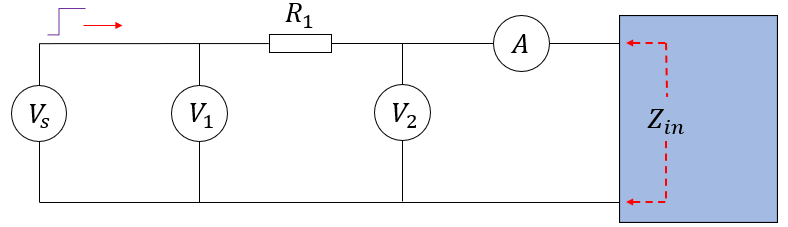
Input impedance is quite easy to measure up to MHZ frequencies as long as the input and output ports in an electrical network are well-defined. In the diagram below, /V1 and V2 are voltmeters, and A is an ammeter. A source Vs with low output impedance is used to sinusoidal signal wave into the network, and the voltage and current are measured.
Conjugate matching to the input impedance sets the reflection coefficient to zero.
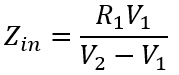
The input impedance can be calculated from the measured voltages at V1 and V2, and the current measured at A. The input impedance is:
By sweeping through a range of frequencies, measurements can be gathered at each frequency and the input impedance can be calculated. This is a much more controlled method than using something like reflectometry off the load network. Once you’re trying to measure the impedance up to GHz frequencies, a vector network analyzer should be used to extract the S parameters, which can then be converted back to impedance values. Note that, at such high frequencies, parasitics in the PCB that holds the DUT become very important and will influence your impedance measurements. As such, the impedance should be measured within its intended environment, and with intended transmission lines and connectors at the input and output ports.
In the above discussion, we’ve looked at time-invariant circuits or harmonically-varying circuits. For continuously time-varying circuits, the above analysis still applies, but all quantities will vary in time, and analyzing signal behavior becomes more complex. This is still an active area of research, particularly when nonlinear components are involved.
Input Impedance of a Transmission Line
What about the case of a transmission line? What impedance will the signal see as it crosses into the conductor system that defines a transmission line? The case of a transmission line is rather easy to understand if we consider the propagating nature of an electromagnetic wave and analyze it in the frequency domain. The transmission lines used to connect components have their own characteristic impedance, and they will be terminated by a source and load impedance. This is shown in the circuit diagram below.

Note that the load impedance could have termination applied; for a high load impedance, the terminator will be in parallel with the load (for example, the input capacitance in an integrated circuit). For a low load impedance, the terminator will be in series.
The load impedance will determine the input impedance value seen by a signal crossing from the source impedance (Zs) into the transmission line. There will be a reflection coefficient defined at the load, which will then appear in the input impedance equation for the transmission line shown below.
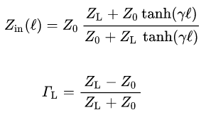
Transmission line input impedance and reflection coefficient definition
Once you know this input impedance, the S11 value will simply be defined by the reflection between the input impedance and Zs. You can read more about S11 and input impedance in this article. Now, depending on the length of the line, we can see how the load impedance affects the input impedance very clearly at any frequency.
Finally, if we are interested in qualifying a channel’s performance and causality using an impulse response, you will need to determine the transfer function of the transmission line. Some basic definitions for transmission lines derived from S-parameters (or equivalently from ABCD-parameters) is shown below.
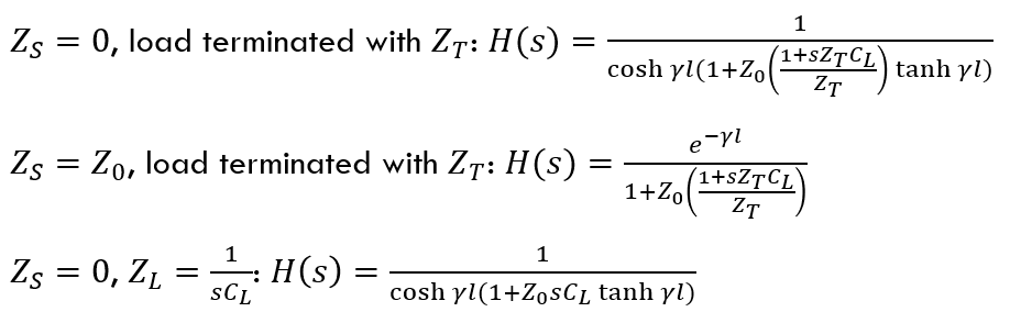
From this, we can calculate the transmission line’s response to any input stimulus in the frequency domain through direct multiplication. The other option is to use convolution with the impulse response function in the time domain and the input test pulse. This set of relations tells you everything needed to simulate a transmission lines behavior, as well as calculate the S-parameters.
Whether you need to design a high speed or RF PCB, we know what is input impedance and how to design your board to ensure signal integrity. We design modern PCBs and create cutting-edge technology for major electronics and electro-optics companies. We've also partnered directly with EDA companies and several advanced PCB manufacturers, and we'll make sure your next layout is fully manufacturable at scale. To see how we can help you with your next design, contact NWES for a consultation.
Ready to start your next design project?
Our Clients and Partners


