
What Bandwidth is Needed for an Arbitrary Digital Signal?
By ZM Peterson • Oct 28, 2020This is a common question in high speed digital design, and it is one that does not have a simple answer. As much as we’d like to think digital signals have a fixed bandwidth, they don’t, contrary to statements from PCB design "experts." Where you cut off the bandwidth of your digital signal and your channel depends on multiple factors, and designers should understand what defines bandwidth limits when designing high data rate communication channels.
How Much Bandwidth Do I Need?
Very simply, the bandwidth needed for an arbitrary digital signal is infinite. If you look at the power spectral density of a digital signal (including pseudorandom bitstreams of multilevel signals), the frequency content extends from DC to infinity. Because of this characteristic of digital signals, many high speed designers that need to design channels to accommodate high data rates begin to question what channel bandwidth is needed for an arbitrary digital signal. Any high data rate channel is also a high speed (i.e., fast edge rate) channel, so a significant portion of the signal’s power is concentrated between at low frequencies, and the channel bandwidth needs to be large enough to allow power to reach the receiver.
The image below shows two example relationships between data rate, number of discrete signal levels, and bandwidth defined in terms of data rate. Two cases (PAM4 and PAM8) are considered and compared with non-return to zero (NRZ) signaling, a binary signaling standard.
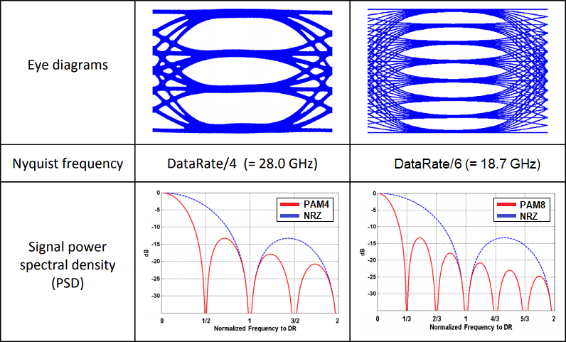
PAM4 and PAM8 vs NRZ signaling and bandwidth
This is one way to set an upper limit on the channel bandwidth and receiver bandwidth; it should be greater than or equal the Nyquist frequency for the signal. If you compare this to the typical knee frequency value calculated from the rise time for ultra-fast signaling standards, you’ll find that typical knee frequency bandwidths extend far beyond the Nyquist frequency, and it may not be practical to design channel bandwidths much higher than the Nyquist frequency. Therefore, the factors that create a bandlimited channel need to be considered when designing high speed interconnects.
There are several factors that will limit the useful bandwidth of a digital signal in a high data rate channel. First, the channel itself can have some defined useful bandwidth, and the receiver has its own bandwidth. These factors can then be used to set an upper limit on the useful bandwidth that can be used to recover a digital signal at the receiver. One should note that these limits on useful bandwidth are the reason equalization is used at the receiver to fully reconstruct a signal.
Channel Bandwidth
If you look at the transfer function for a terminated lossy transmission line, you’ll find that it acts like a low pass filter. This can be seen in an insertion loss plot along a line, and it appears to be the case from the standard circuit model for a transmission line. Obviously, things like via discontinuities, copper roughness, parasitics along the line, and dispersion in the dielectric create variations in the insertion loss rolloff on the line, but generally insertion loss increases with frequency.
The low-pass behavior of a typical transmission line can be seen in the line’s transfer function. An example for a 10 cm lossy single-ended stripline transmission line on FR4 with typical dielectric dispersion and copper roughness is shown below. This line has matched impedance at the source and 50 Ohm shunt termination at a load with 1 pF load capacitance on an 8-layer PCB. Due to matching at the source and DC resistance, we see that this trace has transfer function magnitude of ~0.48 out to approximately 3 GHz, beyond which the transfer function value rolls off. We also see frequent phase reversal beyond ~200 MHz, showing that distortion will occur at higher frequencies.

Transmission line transfer function magnitude and phase.
We could say that this line has bandwidth of ~3 GHz, so this channel could accommodate NRZ signals running at 6 Gbps, or PAM4 signals at 12 Gbps. The distortion that will occur will manifest itself in an impulse response calculation. At some frequency and length, the insertion loss will increase to a high value, and the maximum tolerable insertion loss depends on the signaling standard you’re using. For example, in PCIe Gen5, the total loss budget (i.e., maximum insertion loss) is -35 dB at a bandwidth of 16 GHz. The next limitation to consider is the receiver’s bandwidth.
Receiver Bandwidth
The receiver has its own bandwidth, which is determined by two factors. First, the example above should reveal something important about integrated circuits: the input capacitance, which is a parasitic effect, limits the useful bandwidth of the receiver. I intentionally used a load capacitance of 1 pF, but decreasing this to a more realistic 100 fF extends the bandwidth significantly. This is one reason high speed integrated circuits have become physically smaller; the input capacitance is simply smaller, so the channel bandwidth can remain relatively flat out to higher frequencies.
The other aspect of a receiver that limits bandwidth is its maximum sampling rate, which must be at least as large as the bitstream’s Nyquist frequency. If the bitstream Nyquist frequency is too large, then the receiver cannot resolve all bits in the bit stream, leading to high BER value. A receiver cannot physically operate at any sampling rate, which is why digital transmitters and receivers are paired up for digital communication.
Summary
The example transmission line shown above considers single-ended signals, but real high speed signaling standards can be differential. However, the same ideas apply to differential lines, you simply need to calculate or measure the relevant signal integrity metrics for your differential lines. Empirical equations could be used, or you can use a field solver to determine differential characteristics of differential lines.
Tha above example should also illustrate why pulse shaping filters are used in high data rate communication. When digital data needs to be transmitted over a long link, the limited bandwidth of the channel can corrupt data and leads to intersymbol interference (ISI). By using digital data to modulate a carrier siganl, the bandiwdth of the signal is greatly compressed so that it can be transmitted over a physical medium like copper or fiber. Hopefully, this also illustrates why telecom engineers use the terms "bandwidth" and "data rate" interchangeably; for telecom engineers, they really do mean the same thing thanks to the use of a pulse shaping filter for data transmission.
The design team at NWES specializes in high speed and high frequency board design, and we understand how to accommodate the bandwidth required for an arbitrary digital signal. We work with electronics companies, defense & aerospace companies, and the DoD providing cutting-edge PCB design services. We've also partnered directly with EDA companies and advanced PCB manufacturers, and we'll make sure your next design is fully manufacturable at scale. Contact NWES for a consultation.
Ready to start your next design project?
Our Clients and Partners


