With advancements in wireless communication and mmWave systems, modern RF systems must support more frequency bands, broader bandwidths, and more features than ever before. This has led to the need for multiple antennas in communication devices and unique RF sensors, with some requiring arrays of dozens of antennas. At the same time, hardware developers face challenges in designing compact and efficient RFFE solutions that fit within increasingly small form factors.
Today’s designs are implementing multiple-input multiple-output (MIMO) configurations with configurable arrays and advanced switching mechanisms to track and communicate with multiple objects. For example, we have used these techniques in high-resolution radar systems to provide radar imaging capabilities across multiple objects. These systems often require antenna switches or antenna tuning switches, in order to become configurable at the hardware level.
Antenna Tuning Switches
Antenna switches come in two major applications: switching a feedline between RF antennas (or vice versa for a shared antenna), such as in a dual-band device; and antenna tuning.
Aperture Tuning vs. Impedance Tuning With Antenna Tuning Switches
RF switches are commonly used for an important application: antenna tuning. In lower frequency radio systems, these are large devices that allow the resonant frequency and input impedance into an antenna to be adjusted such that the input signal has maximum radiation efficiency from the antenna. In more advanced high frequency systems, antenna tuning can be performed electronically with an RF switch IC, either as part of design or as part of a built-in calibration technique on an embedded device.
Antenna tuning switches are a particular type of RF switch that is specifically designed for these applications. By increasing the efficiency of an antenna, you boost its sensitivity and thus its usable range, which reduces power consumption in the handset. There are two approaches you can use for antenna tuning:
- Aperture tuning: this approach can boost isotropic sensitivity and radiated power by optimizing efficiency for receiving and transmitting communications at specific frequencies. In essence, this tunes the resonance frequencies of the antenna to desired values by adjusting the equivalent capacitance and/or inductance in the antenna.
- Impedance tuning: the idea is to boost power transfer between the antenna and RFFE. Impedance tuning is normally used with frequency-division duplexing (FDD) to broaden the bandwidth of an antenna within a particular range so that it can receive/transmit with uniform insertion/return in a specific frequency band. Adjusting the impedance spectrum (thus the name "impedance tuning") will boost the isotropic sensitivity and radiated power, as well as decrease the mismatch loss. This approach can help to neutralize environmental factors, such as the user holding their smartphone.
Example Parts: Infineon BGSA13GN10 and Skyworks SKY19256-701LF
Two example parts that support antenna tuning in 5G systems are the SKY19256-701LF from Skyworks and the BGSA13GN10 from Infineon.
Skyworks has designed numerous antenna switch solutions over the years, including the SKY19256-701LF. The SKY19247-701LF is a comparable tuning switch that is operable up to 2.7 GHz. This particular product is an aperture tuning switch. The extensive bandwidth coverage ranges from 600 MHz to 6 GHz, making it useful for numerous mobile platforms working within those frequencies. This antenna tuning switch includes an array of 4 single-pole, single-throw switches that can serve applications with extremely low on-state resistance (1.1 Ohm) and off-state capacitance (0.145 pF).
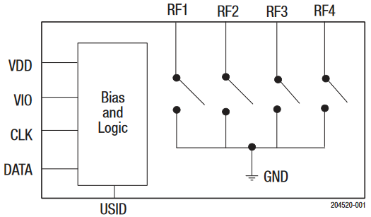
Skyworks SKY19256-701LF block diagram.
Infineon is another well-known company that is developing a comprehensive set of solutions to support 5G rollouts. The BGSA13GN10 single-pull, triple-throw aperture antenna tuning switch supports 500 MHz to 5 GHz frequencies with up to 48 V RF output voltage (39 dBm power delivery).
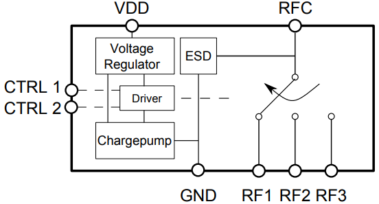
Infineon BGSA13GN10 block diagram.
Antenna Switches For RF Routing
The most common application of antenna switches we have encountered is for systems that need to share a single antenna across two different protocols. A perfect example is WiFi and Bluetooth, which can have channels broadcast in the same (or nearly the same) frequency bands (2.4 GHz). The use of an electronically-controlled antenna switch eliminates coexistence problems for protocols operating near the same frequencies.
As an example, take a look at the application involving nRF7002 and nRF5340, which we provided in an article to our client CELUS. This application uses an antenna switch to swap the connection between shared antenna and two broadcasting/receiving devices (the nRF7002 and nRF5340). The nRF5340 acts as the system host and it controls the switching action, as well as the time window and data the nRF7002 can broadcast.
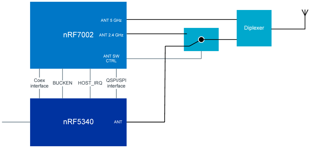
Example application for handling coexistence with an RF antenna switch. Image created for CELUS.
A typical SPDT RF switch IC operating above WiFi frequencies with moderate insertion loss can be used in this application. The Nordic components shown above are available in wafer-level chip-scale packaging (WLCSP) with fine-pitch BGA footprint, which allows them to be used in small mobile devices.
Example Part: Infineon BGS12P2L6E6327XTSA1
The BGS12P2L6E6327XTSA1 is a high-power SPDT RF switch designed to operate across a broad frequency range from 50 MHz to 6 GHz. This versatility makes it suitable for various applications, including LTE and 5G sub-6 GHz communications. The switch boasts low insertion loss and high port-to-port isolation, enhancing signal integrity in demanding RF environments. It can handle input power levels up to 37 dBm, ensuring robust performance in high-power scenarios.
The BGS12P2L6E6327XTSA1 offers the performance benefits of GaAs with the integration advantages of CMOS, including enhanced ESD robustness. The device integrates on-chip CMOS logic, allowing control via a single-pin CMOS or TTL compatible input. Its compact leadless package measures just 0.7 mm x 1.1 mm with a thickness of 0.31 mm, making it ideal for space-constrained designs. Additionally, external DC blocking capacitors are unnecessary unless DC voltage is applied externally, simplifying circuit design and reducing component count.
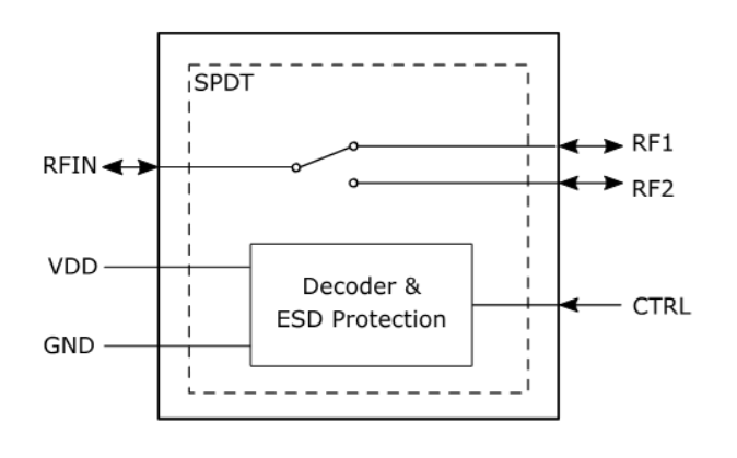
Infineon BGS12P2L6E6327XTSA1 block diagram.
At scale, these components are used in large arrays, and increasingly this is done to make large arrays reconfigurable at the hardware level. It also allows segmentation of an array into sub-arrays. In specialty applications like automotive, this would be performed by RF ASIC transceivers, but with antenna switches and a large processor (FPGA), this can be performed directly on-device. We have designed hardware platforms that can support this approach for small satellites, mmWave sensors, automotive radars, and drone radars.
Whether you're designing high-speed PCBs for mil-aero embedded systems or a complex RF product, you should work with a design and development firm that can ensure your product will be reliable and manufacturable at scale. NWES helps aerospace OEMs, defense primes, and private companies in multiple industries design modern PCBs and create cutting-edge embedded technology, including power systems for high reliability applications and precision control systems. We've also partnered directly with EDA companies and advanced ITAR-compliant PCB manufacturers, and we'll make sure your design is fully manufacturable at scale. Contact NWES for a consultation.
Ready to start your next design project?
Our Clients and Partners


