

In RF circuit design and transmission line design, a reciprocal network is a linear network whose behavior is the same regardless of the direction of signal propagation. In terms of the S-parameter matrix, reciprocity means the S-parameter matrix is symmetric. This applies to single-ended channels and differential channels, the latter of which is very important in high-speed PCB design. In practice, most passive RF components and circuits are reciprocal. Examples include coaxial cables, attenuators, passive filters, splitters, and combiners.
The definition of reciprocity in a reciprocal network is as follows:
- S21 = S12 (forward transmission equals reverse transmission)
- More generally, for an N-port reciprocal network, Sij = Sji for all i, j.
Fundamentally, this symmetry in linear time-invariant networks stems from the Lorentz reciprocity theorem in electromagnetics. In terms of circuit behavior, the mutual impedance or transfer function between two ports is the same in either direction. Thus, a network built from conventional R, L, and C elements (or other linear passive components) will have a symmetric impedance and admittance matrix, leading to a symmetric S-parameter matrix when referenced to the same impedance on each port.
Does Impedance Mismatch Cause Non-Reciprocity?
The simple answer is "no," an impedance mismatch alone does not break S-parameter reciprocity. Impedance mismatch in the context of S-parameter measurements indicates the input impedance at one of the ports is not perfectly matched to the reference impedance (therefore, Sii is not 0). While mismatch affects reflections and port return losses, it does not inherently break the S21 = S12 relationship for a given network. In a truly reciprocal network, the forward and reverse transmission coefficients remain equal, even if the input/output impedances are not matched.
For example, consider a passive two-port like a simple transmission line that is not perfectly matched to the same impedance at each end, such as a driver with resistive output impedance and a load with capacitive input impedance. You may find that S11 and S22 have very different profiles (significant reflections), but as long as the network is made of reciprocal elements, it will still exhibit S21 = S12 (the same complex transmission in both directions).
Example: Same Reference Impedance on Each Port
As an example, take a look at the S-parameters for the differential transmission line as part of a BGA breakout below, which consists entirely of linear time-invariant media. This example assumes the same reference differential impedance of 90 Ohms on each port.

Example mixed-mode S-parameters for 90 Ohm differential microstrips with same reference impedances (100 Ohms) on differential ports 1 and 2. Simulated with Simbeor.
Clearly, there is an impedance mismatch on each port, and impedance mismatch is different at each port despite the fact that the reference impedances are both 90 Ohms differential. The impedance mismatch shows up as unequal S11 and S22, not as a difference between S21 and S12. In other words, mismatch affects how much power is reflected vs. transmitted at each port, but it does not introduce any "one-way" behavior by itself.
Example: Same Reference Impedance on Each Port
In unusual cases where measured or simulated S-parameter data correspond to different reference impedances on each port, a reciprocal device can have a non-symmetric S-matrix in that un-normalized form. However, this is a matter of how S-parameters are defined, not a violation of physics - the device is still reciprocal. Typically, one performs normalization on the data in order to transform to a common reference impedance.
The same BGA breakout routing that was shown above
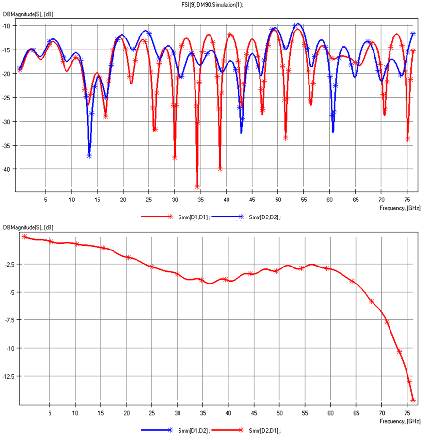
Example mixed-mode S-parameters 90 Ohm differential microstrips with different reference impedances (Port 1: 100 Ohms, Port 2: 80 Ohms) on differential ports 1 and 2. Simulated with Simbeor.
We can again see that shifting the reference impedances to have different values produces a different set of S-parameters, particularly the return loss at both ports. However, it does not impact the insertion loss, and in fact the insertion loss has not changed compared to the previous case with the same reference impedances.
What Breaks S-parameter Reciprocity?
If impedance mismatch alone isn’t sufficient to cause S21 ≠ S12, then what physical conditions are required to break reciprocity? In general, you need some form of non-reciprocal element or medium in the network - something that does not obey the symmetric behavior dictated by Lorentz reciprocity. Key conditions that break reciprocity include:
- Non-reciprocal materials, like ferrites under static magnetic bias, are anisotropic; their electromagnetic properties vary with signal direction. Devices such as circulators and isolators exploit this for one-way transmission, violating S21=S12. These are passive but non-reciprocal, as the magnetic bias breaks Maxwell's equations' symmetry. Thus, networks with magnetically biased or other anisotropic components are non-reciprocal, and their S-matrices are asymmetric.
- Active components like transistors, amplifiers, isolating amplifiers, gyrator circuits, or active circulators are non-reciprocal. They provide gain or have inherent directionality, meaning they don't behave the same in reverse. This is because they inject energy or have powered control favoring one direction of propagation, resulting in unequal forward and reverse transfer (S21 ≠ S12).
- Time-variance or nonlinearity, for example, with a time-modulated component or any parametric time-varying element, violates the LTI assumption in S-parameter theory and can produce non-reciprocal behavior. Non-reciprocity can be achieved without magnetic or anisotropic media through spatio-temporal modulation or nonlinear devices (e.g., diodes or other discrete semiconductors).
Reciprocity breaks when fundamental assumptions (passive, linear, time-invariant, isotropic media) are violated. Networks with non-reciprocal elements (magnetically biased material, active elements, or time-varying parameters) will have a non-symmetric S-matrix (Sij ≠ Sji). Examples include RF isolators (ferrite, one-way), RF amplifiers (active, gain/isolation), and circulators (three-port, directional). Conversely, passive attenuators or transmission lines maintain reciprocity with equal forward and reverse attenuation.
Whether you're designing high-speed PCBs for mil-aero embedded systems or a complex RF product, you should work with a design and development firm that can ensure your product will be reliable and manufacturable at scale. NWES helps aerospace OEMs, defense primes, and private companies in multiple industries design modern PCBs and create cutting-edge embedded technology, including power systems for high reliability applications and precision control systems. We've also partnered directly with EDA companies and advanced ITAR-compliant PCB manufacturers, and we'll make sure your design is fully manufacturable at scale. Contact NWES for a consultation.
Ready to start your next design project?
Our Clients and Partners



















