
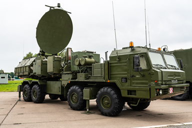
MIL-STD-1275F is a critical testing standard for verifying the durability and dependable operation of electronic equipment used in military ground vehicles. This standard thoroughly evaluates how equipment performs when subjected to various electrical stresses, with a particular emphasis on the 28V DC power input. The goal is to guarantee that the equipment can successfully endure expected fluctuations in power distribution and disturbances emitted within the vehicle's electrical system, thus ensuring operational integrity in challenging military environments.
The evolution from MIL-STD-1275E to Version F represents a paradigm shift in military EMC testing that extends far beyond incremental updates. While MIL-STD-1275E required surge waveforms with approximately 125 mJ energy content, Version F demands over 250 mJ, a 2-fold increase that fundamentally alters design requirements and testing methodologies.
Understanding the Technical Implications
This energy escalation transforms surge testing from a relatively straightforward pulse generation exercise into a sophisticated power electronics challenge. The legacy approach of simple capacitor discharge through basic switching elements becomes inadequate when peak currents and energy storage requirements increase by a factor of two.
| Parameter | MIL-STD-1275E | MIL-STD-1275F | Impact Factor |
|---|---|---|---|
| Energy Content | ~125 mJ | >250 mJ | 2x increase |
| Component Requirements | Automotive-grade | Specialized power electronics | Critical redesign |
| Thermal Management | Minimal | Essential | New design constraint |
| Measurement Bandwidth | Standard EMC equipment | >1 GHz real-time scope | Equipment upgrade required |
Previously negligible effects now become critical design considerations:
- Transmission line effects that distort waveform integrity at higher frequencies
- Impedance mismatches causing reflections and energy loss
- Ground loop inductances affecting pulse rise times and peak amplitudes
- Parasitic capacitances influencing high-frequency response characteristics
Advanced Circuit Design Approaches
Implementing MIL-STD-1275F-compliant test equipment often necessitates moving beyond simple discharge circuits to more sophisticated topologies. Blumlein transmission line generators offer controlled impedance characteristics while delivering the required energy levels, though they require careful design to maintain waveform fidelity across the specified frequency range.
| Topology | Energy Capability | Rise Time Control | Implementation Complexity | Key Advantage |
|---|---|---|---|---|
| Blumlein Generator | Excellent | Very Good | Moderate | Controlled impedance |
| Marx Generator | Excellent | Good | High | Voltage multiplication |
| Magnetic Compression | Good | Excellent | High | Sub-microsecond rise times |
| RC Discharge (Legacy) | Poor | Fair | Low | Simplicity (inadequate for 1275F) |
Marx generator configurations provide voltage multiplication capabilities essential when single-stage approaches prove insufficient. Key design considerations include:
- Parallel charging efficiency to minimize infrastructure requirements
- Series discharge timing for optimal energy transfer
- Insulation coordination across multiple stages
- Component matching to ensure balanced operation
Magnetic pulse compression techniques achieve the demanding rise time specifications while maintaining high energy content, though core material selection becomes critical for predictable saturation behavior across environmental conditions.
Measurement and Characterization Challenges
The 2-fold energy increase demands measurement precision that exceeds typical EMC test equipment capabilities. Real-time oscilloscopes require bandwidth specifications beyond 1 GHz to capture the complete frequency spectrum, as the increased energy often correlates with spectral components extending well beyond fundamental pulse frequencies. Current measurement becomes particularly challenging, requiring precision shunts with sub-nanohenry inductance or Rogowski coil implementations to maintain accuracy across the entire pulse duration.
Statistical process control becomes essential for ensuring repeatable results. Coefficient of variation calculations for critical parameters—peak amplitude, rise time, pulse width, and total energy content—should target values below 5% to demonstrate adequate process control. This level of precision requires automated waveform analysis using digital signal processing techniques and fast Fourier transform analysis extending to at least the 10th harmonic of the fundamental frequency.
Common Interpretation Challenges in MIL-STD-1275F
MIL-STD-1275F's documented clarity issues create particular challenges for test engineers developing compliant equipment. The standard's loose definitions require systematic approaches to ensure consistent implementation:
Documentation Requirements:
- Maintain detailed records of parameter interpretations with technical justification
- Document all measurement methodologies and uncertainty analyses
- Establish clear traceability to specific standard requirements
- Version control all interpretation decisions for audit purposes
Stakeholder Engagement Strategy:
- Direct communication with standards committee members for ambiguity resolution
- Technical discussions supported by oscillograms and waveform analysis
- Participation in industry working groups addressing implementation challenges
- Proactive engagement regarding anticipated future revisions
The ongoing discussions regarding potential revisions to frequency characteristics add complexity that requires flexible test equipment architectures. Programmable pulse generation systems or modular designs enable reconfiguration as requirements evolve without complete hardware redesign.
Thermal and Safety Considerations
The table below outlines how the MIL-STD-1275F standard impacts the design approach for military vehicle electronics.
| Component Category | MIL-STD-1275E Impact | MIL-STD-1275F Requirements | Design Response |
|---|---|---|---|
| Switching Elements | Standard SOA adequate | Often exceeds SOA limits | Thermal derating required |
| Energy Storage | Minimal heating | Significant I²R losses | Active cooling systems |
| Protection Circuits | Basic overcurrent | Multi-level protection | Redundant safety schemes |
| Measurement Shunts | Standard precision | Sub-nanohenry inductance | Specialized designs |
The dramatic energy increase introduces thermal management challenges that were negligible under MIL-STD-1275E. Junction temperature analysis becomes essential for preventing semiconductor failures, as instantaneous power dissipation often exceeds safe operating area limits for previously adequate devices.
- ESR specifications optimized for high-current pulse applications
- Ripple current ratings exceeding calculated RMS values by 150% minimum
- Active balancing circuits for series-connected elements
- Thermal monitoring with automated protection systems
- Voltage imbalance prevention within ±2% across all elements
Thermal imaging analysis helps identify hotspots and thermal gradients during high-repetition-rate testing, enabling proactive design modifications before component failures occur.
Implementation Strategy
Successful transition to MIL-STD-1275F compliance requires a phased approach that acknowledges both the technical complexity and the standard's interpretive challenges. Initial development should focus on achieving clearly defined requirements while documenting interpretation decisions for ambiguous areas. Stakeholder engagement throughout development helps validate approaches and identify potential compliance gaps before formal testing begins.
The transition to MIL-STD-1275F represents a significant evolution in military EMC testing capabilities that demands careful attention to both technical implementation and standards interpretation. Success requires moving beyond traditional approaches to embrace advanced power electronics design principles while maintaining the rigorous documentation and traceability standards expected in military testing environments.
Whether you're designing high-speed PCBs for mil-aero embedded systems or a complex RF product, you should work with a design and development firm that can ensure your product will be reliable and manufacturable at scale. NWES helps aerospace OEMs, defense primes, and private companies in multiple industries design modern PCBs and create cutting-edge embedded technology, including power systems for high reliability applications and precision control systems. We've also partnered directly with EDA companies and advanced ITAR-compliant PCB manufacturers, and we'll make sure your design is fully manufacturable at scale. Contact NWES for a consultation.
Ready to start your next design project?
Our Clients and Partners



















