Example PCB Design Projects by NWES
We've made some of our favorite design examples available for community use on this page. These design examples were created for EDA clients or have been approved for public release by past design clients. All design files are available under a Creative Commons license (CC BY-NC-SA) for non-commercial usage. As more designs are created, we'll add them to this page.
By downloading these files, you acknowledge that you accept the Website Terms of Service and the Terms and Conditions on Usage of Open Source Designs.
Disclaimer: components or circuits used in these designs have not been evaluated by semiconductor vendors and NWES makes no guarantee of functionality. By viewing, opening, downloading, using, or otherwise interacting with these design examples in any way, you agree that NWES shall not be held liable for any malfunctions, injury, or damages arising from the use of these example designs. NWES will not review your design, provide usage advice, or provide free design guidance for these example projects. Any user that downloads, modifies, manufactures, distributes, sells, or otherwise uses the design data posted here does so at their own risk. For more information, see our Terms of Service page.
Table of Contents
| Project Name | Download |
|---|---|
NFC Reader With RelayPN: NFCREAD-001, Last updated: July 2025 (Rev A)
This ESP32-based NFC reader uses the TRF7970A for short-range communication based on the ISO-14443A standard. The also includes a relay, which is toggled by the ESP32 microcontroller in order to switch an external device. There are additional holes on the PCB which connect to LEDs based on the presence of an ISO-14443A compatible tag. These outputs are connected to the ESP32 GPIOs, so they can be used to toggle a variety of devices. Major components include: |
Link |
ESP32 Circuit Mind PCBPN: CMPCB-001, Last updated: January 2025 (Rev A)
This ESP32-based IoT PCB was created for Altium Academy in collaboration with Circuit Mind. The design includes multiple sensors and an integrated Bluetooth antenna. The design is intended to run off of 5V input power and includes a low-profile Hirose connector for interfacing with a host PCB via a flex ribbon. Major components include: |
Link |
PCIe Edge Card x16 TemplatePN: PCIECARD-001, Last updated: December 2024 (Rev A)
This PCIe edge card template (x16 lanes) was created for Altium Academy (link to article and YouTube video) by viewer request. The card template project contains an example board outline, mechanical keying format, and the pinout for a 16-lane edge card. The pinout connects to AC coupling capacitors which are included only for reference and example placement on PCIe lanes. |
Link |
Ethernet Switch With SFPPN: ETHSWSFP-001, Last updated: August 2024 (Rev A)
This 13 port Ethernet switch includes 12x 10/100 ports, 1x Gbps Uplink port, 1x serial port, and 1x 2.5 Gbps SFP port for a fiber optic connection. This switch design is a variant of a small form factor Ethernet switch for a data center client. It is based on a Vitesse chipset with an expansion PHY. It is compatible with the VSC742x series of Ethernet controllers and could be swapped with a higher-end part number to provide higher port count. Major components include: |
Link |
6 GHz RF Signal GeneratorPN: PWRMOD-001, Last updated: May 2024 (Rev A)
This module generates a 6.3 GHz signal from a local oscillator and outputs over an SMA connector. The device includes a compact, low-noise regulator for generating the main bus voltage and a dual-rail regulator for generating the amplifier gate voltages. The amplifier on the device is listed with a maximum frequency of 6 GHz, but the response curves in the datasheet indicate the component can work up to approximately 8 GHz. Consider adding one additional header on the VTUNE net for the VCO so that the generated frequency can be manually adjusted if needed. Major components include: |
Link |
3.3V Output Flyback Converter ModulePN: FLBACK-001, Last updated: February 2024 (Rev B)
This module converts 120 VAC RMS at 60-400 Hz to 3.3 V DC output. The module uses a custom transformer and the UCC28881 for switching. The flyback converter operates in voltage-control mode. Major components include:
|
Link Rev A |
nRF52 Module With Battery PowerPN: NRFMOD-001, Last updated: September 2025 (Rev B)
This Bluetooth module is based on the nRF52 WLCSP fine-pitch BGA package. Includes an EEPROM, programming header, I/O header, batter connector, and power/battery management. USB charging is not included at this time. Major components include: |
Link Rev A |
Dual ADC ModulePN: ADCEX-001, Last updated: December 2022 (Rev A)
This ADC module includes a rad-hard power regulator from Intersil and two ADCs: 1 isolated ADC and 1 non-isolated ADC. Input signals for the ADC and isolated +5V power are provided through 3 SMA connectors. An I/O pin header is included for access input/output data and programming the non-isolated ADC. Major components include: |
Link |
USB to UART BridgePN: USBUART-001, Last updated: January 2023 (Rev A)
This module provides USB-to-UART conversion in a small form factor. The device includes additional ESD protection on the input and output sides of the device for added reliability. Additional protection could be implemented with an enclosure and a chassis guard ring applied to the board edge. Major components include: |
Link |
USB to UART via RJ-45 ModulePN: UARTETH-001, Last updated: April 2023 (Rev A)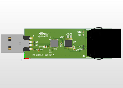
This module provides USB-to-UART conversion over a shielded Ethernet connector for interfacing with networking equipment. This small form factor device is an alternative to older RS-232. The device includes additional ESD protection on the input and output sides of the device for added reliability. An enclosure and a chassis guard ring on the PCB could be used for additional ESD protection. Major components include: |
Link |
LED Shield for Arduino UnoPN: LEDSHL-001, Last updated: June 2023 (Rev A)
This shield board for an Arduino Uno was originally created for the Altium Education program. This board includes a 12V to 5V regulator circuit and two CREE LEDs. It has been modified from its original version to include a 2-pin header for power input. Major components include: |
Link |
USB Charger ModulePN: USBCHG-001, Last updated: January 2023 (Rev A)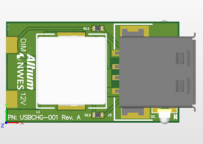
This 2-port USB charger module operates at 12 V input with maximum power output of 15 W at 5 V (3 A maximum current) per port. This device uses edge connections for a pluggable interface, although it could be modified to include a through-hole connection to a pin interface or flying leads. Major components include: |
Link |
Our Clients and Partners


